Rolleiflex 2.8F Light Meter Rebuild [Part #2]
Introduction
In part #1 of this series, I described how I replaced the original selenium cell of my Rolleiflex 2.8F with a DIY light meter based on a microcontroller circuit. This part will focus in more detail on the circuit design of the meter.
The Existing Circuit
The original Rolleiflex light meter consists of two components:
- A selenium cell which delivers an output voltage depending on the light level
- A galvanometer which displays this voltage as a needle movement. The user then sets the exposure by matching a built-in mechanical indicator to the needle position.

Fig. 1: Schematic of the Rolleiflex light meter
The selenium cell generates a current, therefore no additional battery is needed. This makes up for much of the appeal and simplicity of early selenium light meters in general. While other meters of the time used additional resistors to calibrate the circuit, Rollei decided to leave out even that. However, this meant that (due to sample variations of cells and meters) they had to pair each individual selenium cell with a galvanometer which matched the output of the cell as close as possible.
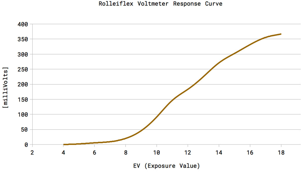
According to my measurements with a multimeter, the Rolleiflex galvanometer in my camera reaches its maximum needle swing at a voltage of 367mV. The aperture/exposure indicator at this position corresponds to a light level of EV 18. The cell in my camera only did much less than that and maxxed out two-thirds through the meter range at around EV 14. Of course, this affected all other light levels as well, which is why I wanted to replace the cell in the end.
Galvanometer Response: The Key Issue

Fig. 2: Galvanometer needle position vs. input voltage