
Rolleiflex 2.8F Light Meter Upgrade [Part #5]
An update to my original series of articles from 2017 on a DIY custom light meter for the Rolleiflex 2.8F film camera.
Earlier Articles From 2017
Update From The Future In 2024
Many years have passed since I published some details of my Rolleiflex light meter contraption, links to which you can find above. Fast forward to 2024, and unfortunately my late Rolleiflex did not make it to this day. However, I did make some further and significant improvements to my light meter after I published the original articles. While the hardware is no longer with me today, some photos and tidbits of information on the improved build are still collecting dust on my hard drive. I would like to share them here for the sake of completeness; maybe someone out there might be able to take something away from this for their own project.
Overview
While my initial attempts yielded a working proof of concept, I wasn’t really satisfied with the result yet. Stuffing the electronics in the mirror box and running cables struck me as a not very elegant approach. The genuine Rolleiflex light meter was self-contained behind the nameplate and I wanted to come closer to that original, modular design somehow.
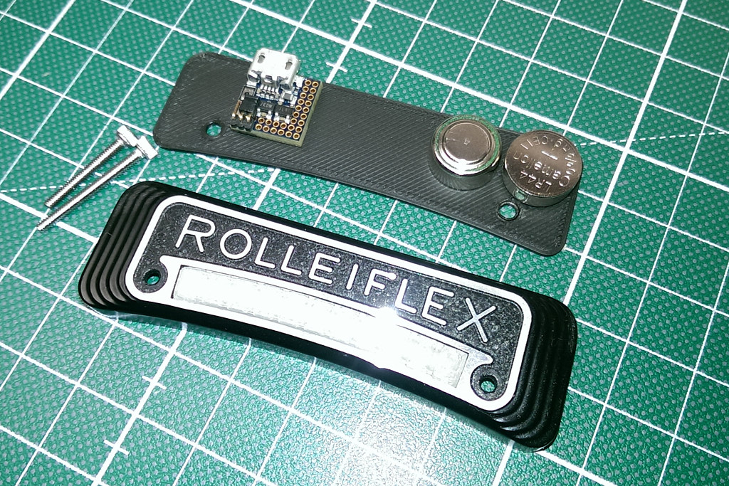
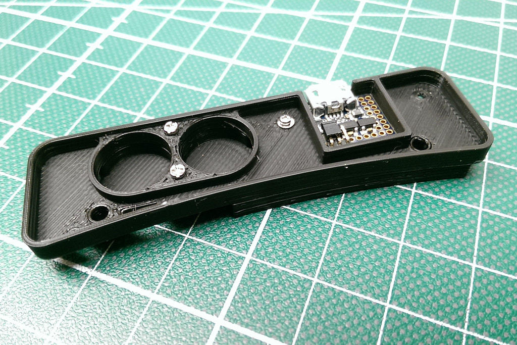
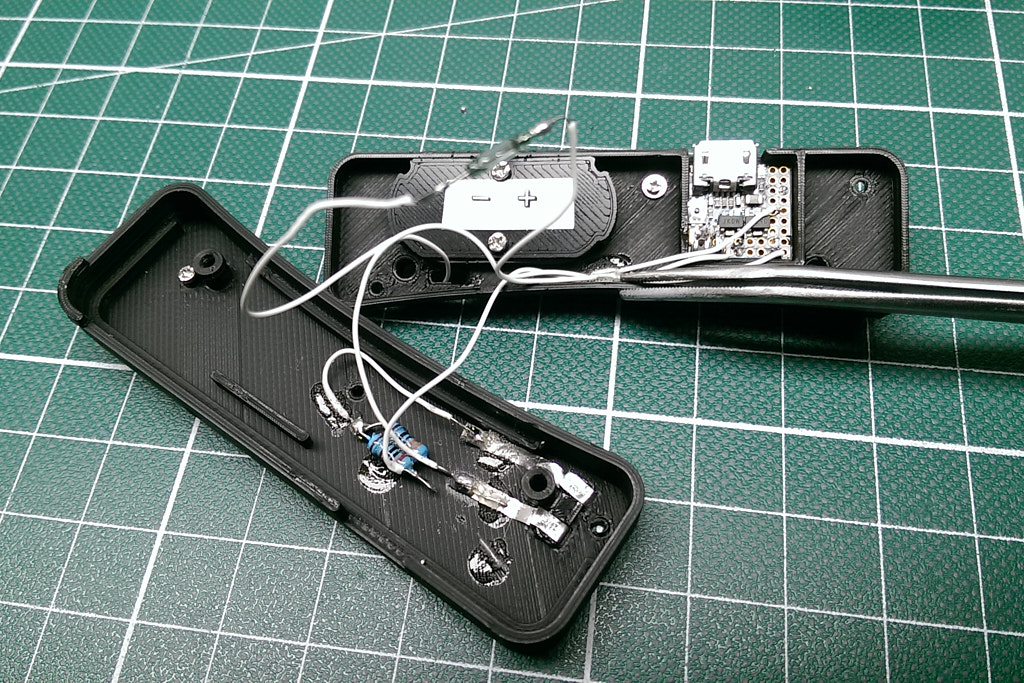
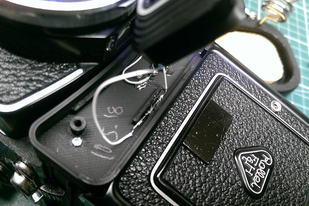
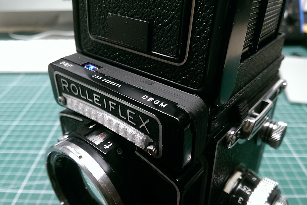
After the first iteration of my project, I soon acquired my first 3D printer. This opened up a new world of possibilities for my DIY projects. For my Rolleiflex, I ended up designing a 3D printed case which would fit between the nameplate and the camera body. My new goal was to fit the entire circuitry and wiring behind the nameplate.
Enter the „uduino”
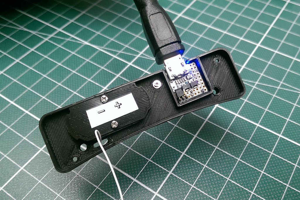
Of course, the original Arduino microcontroller was way too big to accomodate that. At the time however, I discovered a super tiny version of the Arduino microcontroller: the "uduino" which fit on a thumbnail and was perfectly suited for my purpose. This was a crowdfunded project and I was able to get my hands on a sample before it was eventually discontinued. Today in 2024, the uduino no longer seems to be available anywhere. However, devices with a similar small form factor might have evolved in the meantime; I have not looked into this.
The uduino was just about small enough to fit behind the nameplate. Also, it supported 3.3V power mode and even turned out to work close to 3.0V (in contrast to the stock Arduino, which would absolutely not run reliably below 3.3V).
That meant that I could run the circuit off a CR1/3N cell or 2x LR44/SR44 cells (I eventually chose the latter) without the need for an additional step-up converter. One component less.
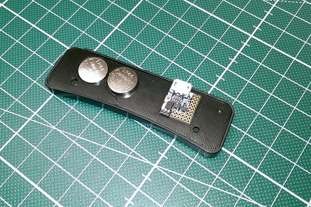
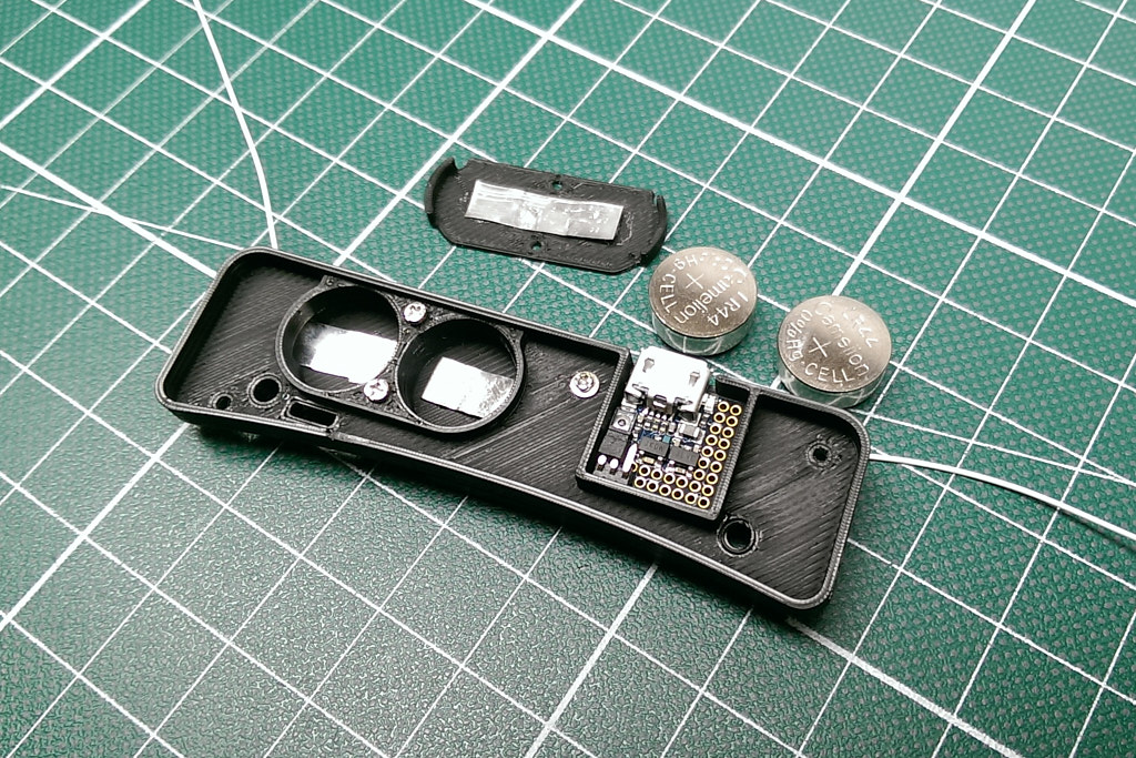
Notes On The Power Supply
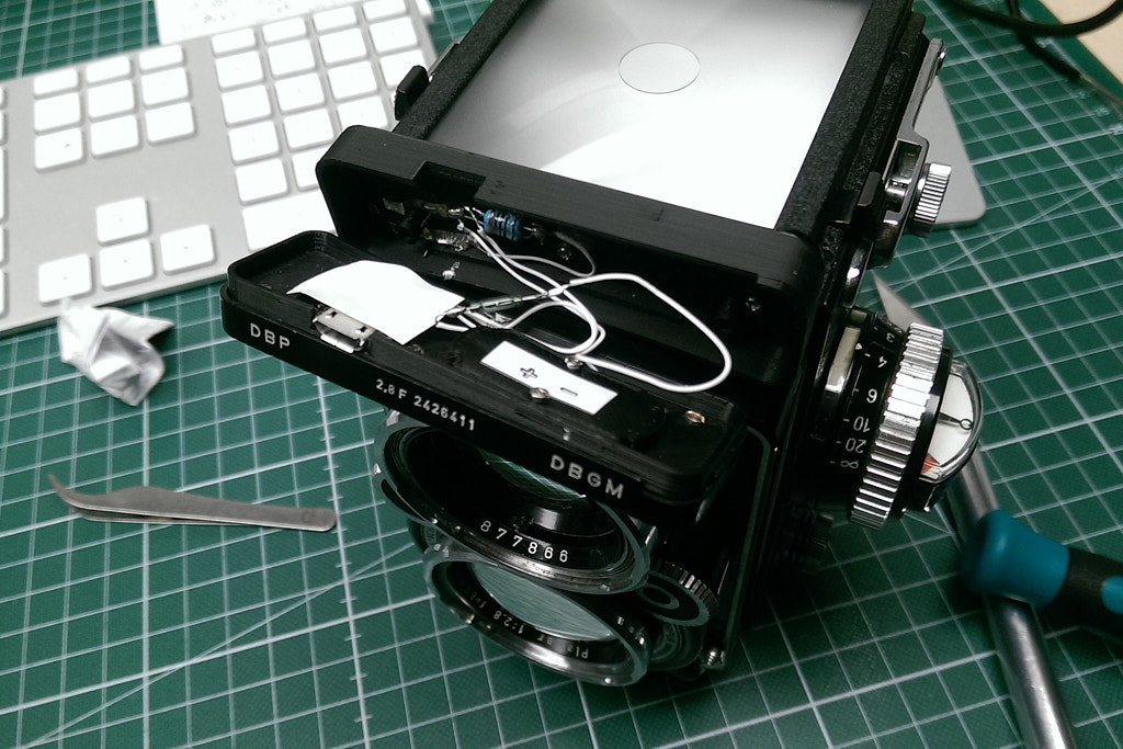
While the photos above depict an arrangement with 2xLR44 cells, I actually built one more version with an even thicker 3D printed casing which was able to house a CR2 lithium cell. Unfortunately I don’t have any pictures of this anymore. The CR2 version was so thick that it covered most of the camera's aperture/shutter display on top of the upper lens, which turned out to be somewhat of an inconvenience. On the other hand, the CR2 battery provided longer battery life and more reliable power without voltage sag even in the freezing winter cold. It also was easier to replace in the arrangement I built.
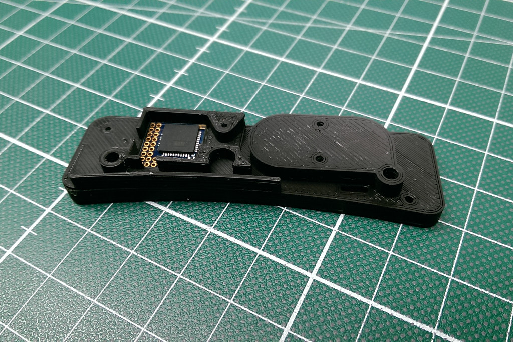
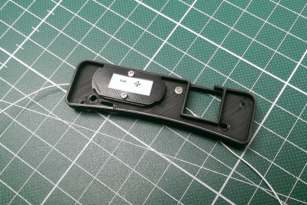
The Power Switch
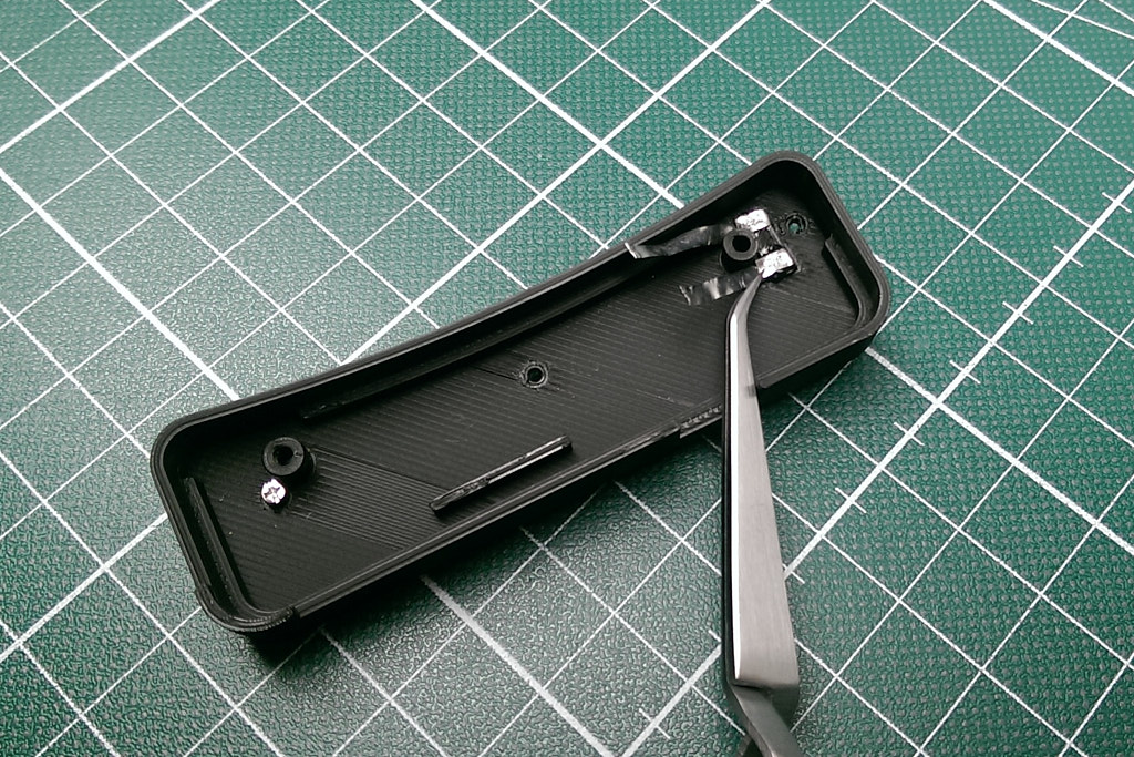
As with the original version, I used a reed sensor again to power up or shut down the light meter automatically whenever the top lid was opened or closed. In this „enhanced version”, I positioned the reed sensor in the center near the top of the nameplate. I took a thin rectangular Neodym magnet (like those found in kitchen cabinets), painted it black and glued it to the top lid of the viewfinder with rubber cement (I chose the weakest glue I had to avoid damaging the original camera finish).
Summary
Most of the build described above was based on the now discontinued uduino microcontroller and on a 3D printed insert between the camera body and the nameplate. This obviously might not be everyone's cup of tea from an aesthetic point of view. However, the main takeaway is that a similar and perhaps less obtrusive design than mine might be possible with small microcontrollers still in production today. If I were to do this all over again, I’d also look into having the case machined out of aluminium (ideally anodizing it in black) and having a single PCB layout manufactured with SMD components.