Rolleiflex 2.8F Light Meter Upgrade [Part #1]
The Problem With Rolleiflex Meters
As much as I like my Rolleiflex, I never was able to come to terms with its aging and increasingly inaccurate selenium cell light meter. As most of you in a similar situation will know, Rollei originally designed the meter such that selected selenium cells and meter assemblies were matched to each other at the factory based on their electrical characteristics. As a consequence, cells and meters were only available as complete replacement kits and could not be exchanged individually without compromising the accuracy of the meter. Today, it is very hard to find such a replacement kit, let alone at a reasonable price. And even if I could acquire one, I would have no guarantee that this one would not die as well in a week, or a year.
An Important Note Before We Start
This article in 4 parts describes a design which was later superseded by an improved version. To understand the motivation and concept of the project, I suggest reading all parts. If you plan on building a similar device though, I’d suggest to take a look at the later iteration of the project as described here.
No Handheld Meter, Please
Most commonly, people suggest to simply use a handheld light meter instead. However, the engineer in me felt quite frustrated by the prospect of having to carry along an additional metering device when one is already built into the camera (it just isn’t working right).
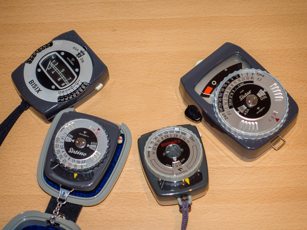
Fig. 1: An assortment of light meters, all too big for me
It took me some time and many iterations to find a technical in-camera solution which would (a) work accurately and reliably over a wide range of light levels; (b) not impact the appearance and intended function of the camera; (c) be non-destructive and 100% reversible, without damaging or permanently altering any part of the original camera.
Starting with the most obvious approach – scavenging a selenium cell from a working handheld meter – a number of attempts with various photosensitive devices and analog circuits of varying complexity failed. It was impossible for me to match the output characteristics of the photo sensors to the very peculiar input response curve of the Rolleiflex analog meter in every part of the intended metering range. I therefore finally resorted to a microcontroller circuit which could be precisely tailored in software to produce the exact needle movement required for any given light level.
Inspiration and Credits
The project described here was inspired in no small part by Sven Keller's excellent account of his own modification of a Rolleiflex light meter. In contrast to my solution, his approach relies exclusively on an analog electronic circuit. Being a software engineer, I felt that a microcontroller solution would be easier to install and require less soldering and cabling. In hindsight, I would say that I was quite wrong… 😅
The Digital Fix
My resulting assembly consists of three parts:
(1) a photo sensor and some supporting components which replace the original selenium cell in the front housing. Since the transparent cover below the „Rolleiflex“ logo is attached to the selenium cell assembly, I molded a duplicate with epoxy plastic based on the original. Thin modding wires run through the thread of the center screw behind the front housing to the inside of the viewfinder mirror case.
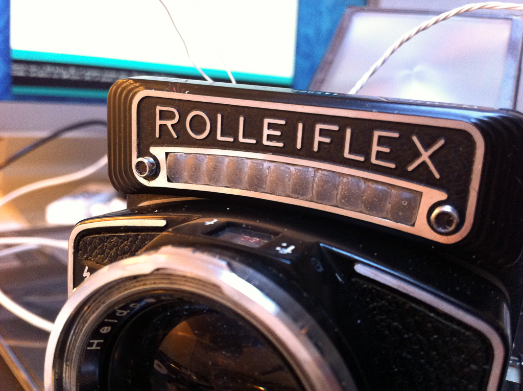
Fig. 2: The epoxy mold replacement for the original selenium cell cover
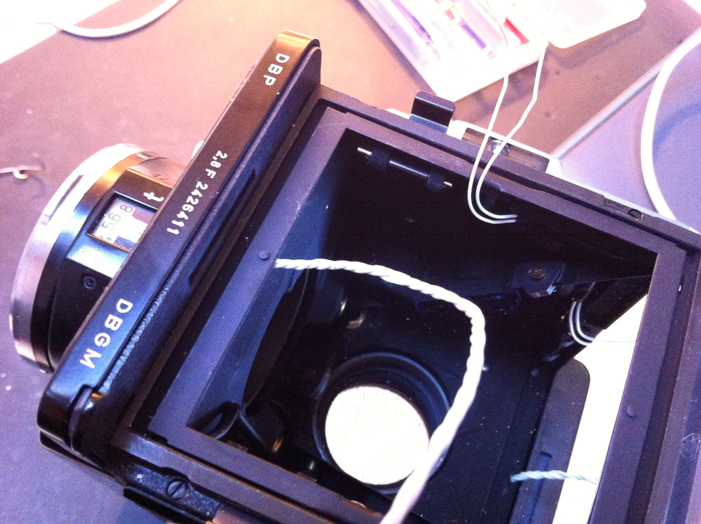
Fig. 3: Wires connecting the front housing with the interior
(2) A microcontroller circuit powered by a 3V battery. The microcontroller is connected to the photo sensor via the aforementioned modding wires. Its basic purpose is to interpret the measured light level and to drive the needle of the original Rolleiflex galvanometer to the corresponding position. I measured the unique response curves of the photo sensor and the galvanometer beforehand and programmed them into the microcontroller firmware. The software also smooths the needle movement to prevent spikes and erratic jitter in fluctuating light.
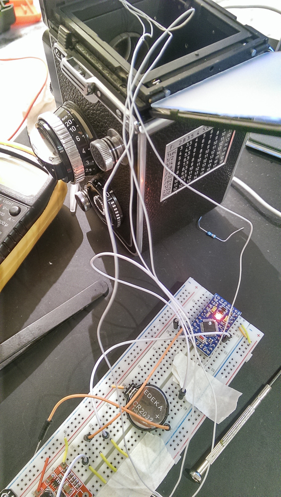
Fig. 4: Experimenting with the circuit design
(3) A power off/on switch implemented with a magnetic Reed sensor in the mirror case and a small neodymium magnet attached to the folding viewfinder hood. As soon as the hood is opened, the sensor connects the battery to the circuit and the microcontroller powers up within a second. When the hood is closed, the circuit shuts down. Based on my calculations, battery life should theoretically support 16 hours of operating time (i.e. total time while the hood is open), but it remains to be seen how this works out in practice.
It’s been quite a challenge to fit everything into the front housing and the mirror case and not obstruct the ground glass image in the viewfinder. A better solution would probably be to use a 3D printer or CNC mill to create a (albeit larger) replacement for the front housing which would contain the entire electronics, but I had to make do with what I had at hand. In the end, the entire system works as intended over a range of EV 4…18. As long as you don’t open the hood, it’s easy to forget that the interior of this analog masterpiece is now stuffed with electronics :)
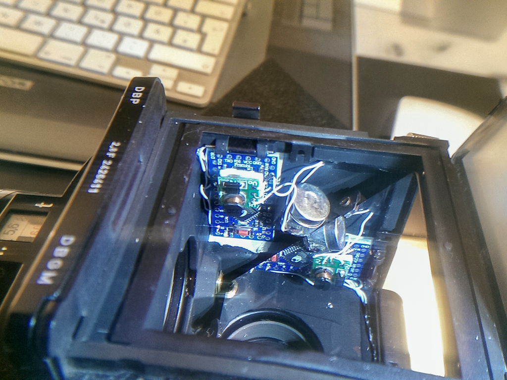
Fig. 5: Final setup – everything crammed in place
Coming Up…
In part #2 of the series, I will describe the design of the light meter in more detail.