
Rolleiflex 2.8F Light Meter Upgrade [Part #3]
Continuing part #2 of the series on my Rolleiflex light meter upgrade, we now take a look at how all electrical components fit together in the tight available space of the Rolleiflex camera body.
Earlier Articles
Physical Layout
Light Meter Housing
The selenium cell in the front light meter housing is firmly attached to a thin metal backing board together with the transparent diffusor. Therefore, the entire assembly (backing board, cell, and diffusor) must be remove if we wish to do this upgrade in a non-destructive manner and preserve the original components (for possible restoration of the camera to its original condition, if necessary).
The light meter housing can be taken off by unscrewing the two screws visible from the front with the help of a thin sewing needle.
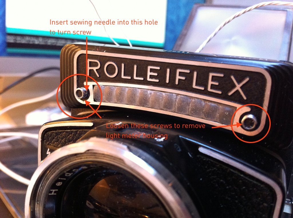
Fig. 1: Removing the light meter housing
The metal board inside can be removed by unscrewing two screws with a small flathead screwdriver.
Now, we need to make a replacement for the original board. This construction will host the LDR photo sensor and its accompanying resistor. Also, since the two electrical contacts on the original board fed the voltage output of the selenium cell to the meter, the two resistors for our galvanometer's voltage divider will go into the front housing too. Putting all those resistors here will greatly simplify the layout of the remaining circuit in the mirror housing.

Fig. 2: Layout of the circuit components in the light meter housing
I used a thin sheet of model building plastic cut to size, as well as solar panel metal strips and glue to hold everything in place. A more professional hobbyist might be able to accomplish all this more efficiently with a custom SMT circuit board.
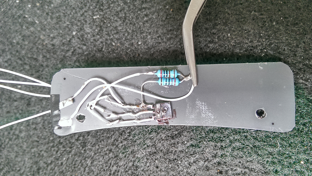
Fig. 3: Components and contacts glued onto the plastic board
Note that the above photo shows an older version of my efforts with a different photo sensor and only two of the 3 resistors in place. I don't have a photo of the actual latest version with the LDR and one more resistor, but I hope you get the idea.
Light Meter Diffusor
To fabricate the light meter diffusor, I squeezed the original mounting board with the diffusor on it into some modeling clay to create a mold. I then filled the mold with transparent epoxy and let it harden. This resulted in a quite nice replacement diffusor which you can see in Fig. 1 above.
- Translucent liquid epoxy with hardener
- Molding clay
- Molding tools – Pack of 6
- Wooden swabs (for stirring epoxy)
- Latex gloves
Internal Mirror Housing
The remaining circuit (Arduino, DC booster, battery, and Reed contact) is crammed in the right side of the Rolleiflex mirror housing, which miraculously offers just enough space for everything to fit in. Everything is soldered together with thin wrapping wire.
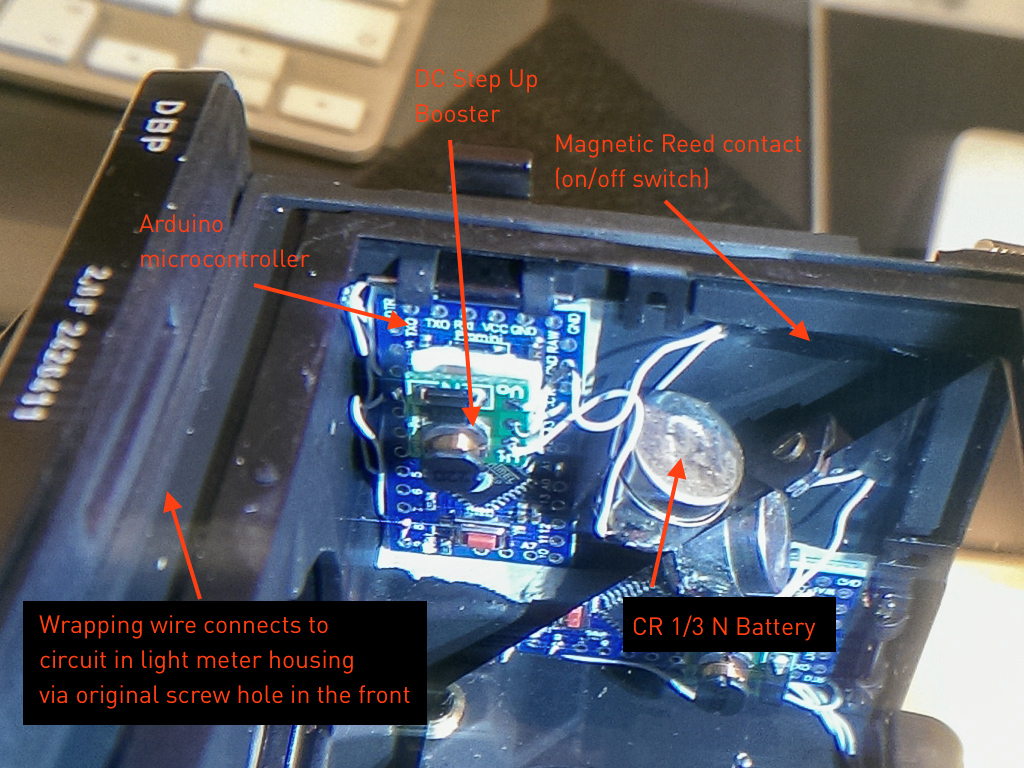
Fig. 4: Circuit arrangement in the mirror housing
The connections to the components in the light meter housing are also accomplished with wrapping wire. When the light meter housing is taken off, three small screws on the camera body become visible. The center screw can be removed so that we have a tiny hole through which we can feed the wrapping wires connecting the light meter with the microcontroller.
Finally, I have fabricated a tiny battery holder from some metal and plastic strips glued together. This is because I was unable to find a commercial holder for a CR 1/3N battery which was small enough to fit in together with everything else.
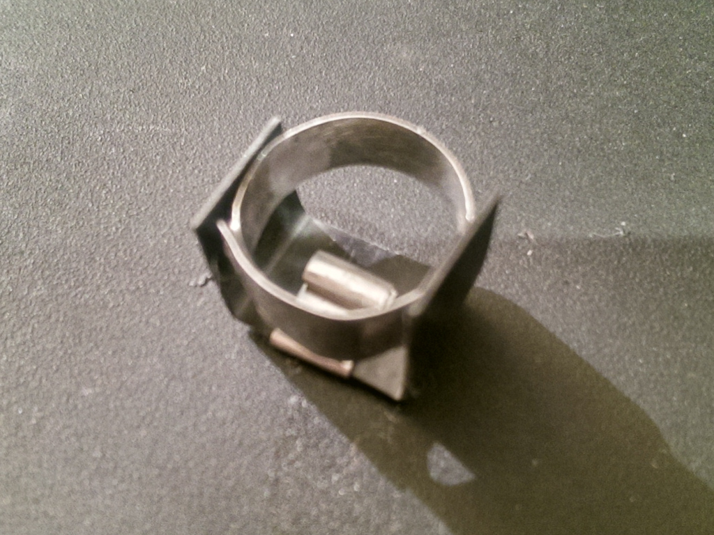
Fig. 5: Self-made CR 1/3N Battery Holder
- Soldering fixture with loupe
- Soldering iron with accessories
- Fireproof desktop mat for soldering
- Thin wrapping wire
- Double-sided mounting tape
Further Reading
In the final part of the series, I will explain the microcontroller source code required to drive the light meter.