
Rolleiflex 2.8F Light Meter Upgrade [Part #2]
Following up on part #1 of my series about replacing my Rolleiflex selenium light meter with a microcontroller-based circuit, this article details the circuit layout.
Earlier Articles
- Part #1: Overview
Electrical Layout
Overview
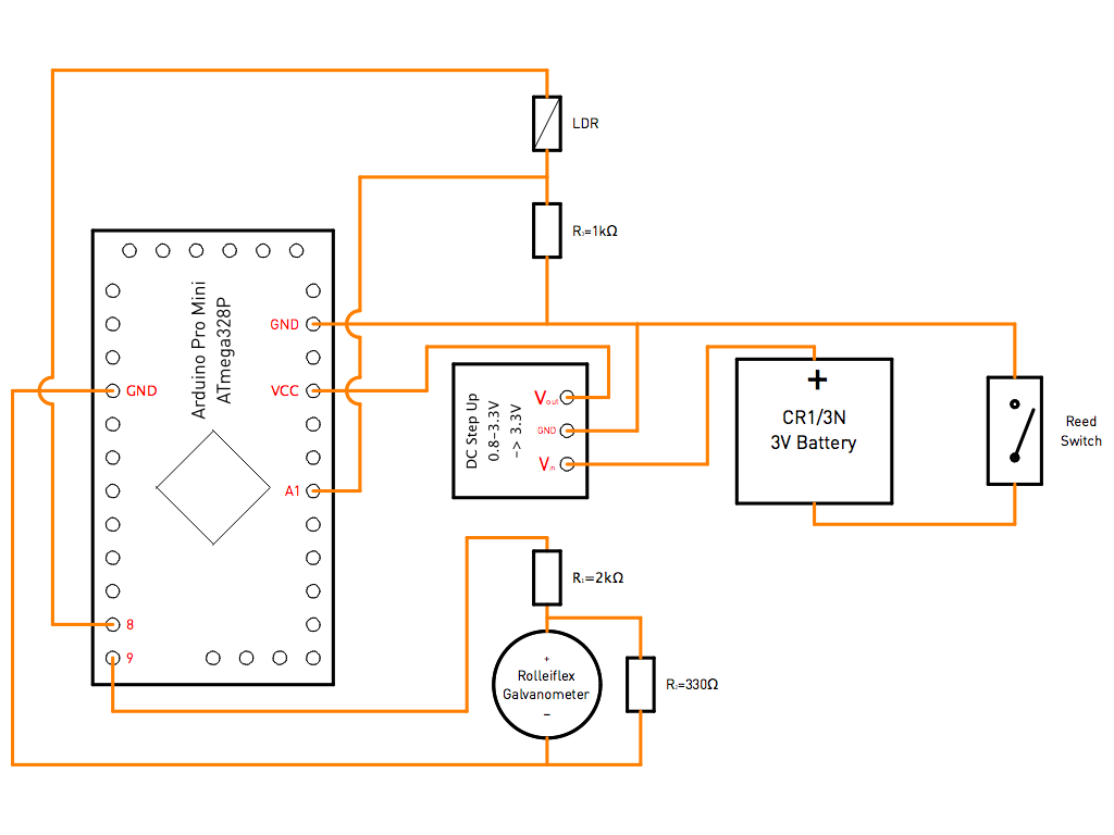
Power Supply
The entire circuit is powered by a CR1/3N 3V battery. This is the smallest battery with sufficient output power I could find which would fit into the Rolleiflex mirror enclosing along with the other components. However, since it only is a 3V battery, a DC "step up" module is required to boost the battery voltage to the 3.3V required by the Arduino controller.
Theoretically, the Arduino should also work with the 3V battery connected to the "raw voltage" (RAW) input. However, the circuit would then be running on an unregulated voltage level, and a drop in battery power would lead to false light level readings of the LDR circuit, which depends on a constant reference voltage.
- Arduino PRO Mini 3.3V 8MHz microcontroller board
- FTDI Adapter FT232RL USB to TTL Serial for Arduino PRO Mini
- CR 1/3 N Batteries – Pack of 3
On/Off Switch
Since the cell in a selenium light meter is always "on" and does not require a power switch, the Rolleiflex camera has no provisions for such a switch either. To avoid battery drain, I have therefore implemented an on/off switch with a magnetic Reed sensor in the mirror housing. A small Neodymium magnet sits in the flap cover above the ground glass. If the cover is closed, the magnet is close to the Reed sensor and breaks the connection between the battery and the circuit. If the cover is opened, the magnet moves away from the sensor. The battery connects to the circuit, and the microcontroller software starts to execute and show light levels after about 1 second.
Light Meter Side
A standard LDR (light dependent resistor) measures the ambient light level. Since the range of possible resistance values is huge (several kΩ in full brightness up to several mΩ in darkness), the LDR is connected to the Arduino in combination with a 1kΩ resistor (R3) to form a voltage divider. Pin #8 provides a reference voltage of 3.3V to the LDR circuit, and the output of the divider is fed back into analog/digital converter pin #A1 of the controller.
Galvanometer Side
The Arduino generates an analog output voltage on pin #9 in proportion to the incoming light level. The output range is between 0V (darkness) and 3.3V (maximum light level) with a possible resolution of 8 bits in software (= 256 steps).
However, the built-in galvanometer in my Rolleiflex only has a maximum range of 367mV. To maintain as much of the 8-bit resolution as possible, a voltage divider (R1=2kΩ and R2=330Ω) reduces the maximum 3.3V output to 467mV at the galvanometer input. This means that 200 steps are available in software to control the light meter. While this could be optimized with a better choice of resistor values, I had to use what was available. In practice, movement of the galvanometer needle is smooth and it is definitely hard to tell that it is actually being driven in discrete voltage steps.
Further Reading
In part #3 of this series, I will describe the physical arrangement of the circuit in the Rolleiflex body.